 Automaton3D Quantum
This application is the Quantum edition of the Automaton3D application, which is also freely available at the Atomic Concepts web site. The automata created in the quantum edition are identical to those created in the original 3D version. The only difference is that the process of constructing and displaying the automata happens immediately, without the need to wait until the final structure has been calculated and displayed. This is possible by pre-calculating the duration of time required, given the automaton's specification, for each of the automaton's points to complete one full cycle of movement (i.e. for each point to return to its initial position in space). Then the final form of the automaton can be immediately displayed. In order to understand how the final form is achieved, it is advisable to first experiment with the original Automaton3D application in order to see how the resulting automaton is created and to compare the two versions.
Other than the ability to pre-calculate and display the automaton, there a couple of subtle differences between the two versions of this application.
- The size relationships between spheres is required to be a rational number, expressed as a whole number part plus a fractional part. This is necessary to exactly calculate the duration of the automaton's cycle.
- The time relationships between child and parent PAIRS of spheres has been simplified.
- The types of dynamic movement that are allowed have been reduced to only 2 types which produce interesting changes in the automaton. Remember that each particle in an automaton can have its own dynamic changes.
An automaton is any mechanism whose movement or operation follows automatically from its design or programmed instructions. Once set into motion, the automaton carries out its movement or action without need of additional instructions and without intervention from outside agents
The automata which are modeled in this application are composed of a set of spheres, each rolling upon the surface of one other sphere in a fully deterministic pattern in space and in time. Because an automaton must have a finite number of spheres, one of the spheres cannot be rolling along the surface of another and so that sphere is made to be stationary relative to the viewpoint. The paths through space taken by one or more points within each sphere can also be visualized as the automaton carries out is choreographed movements.
Spatially, each sphere has a set of child spheres which roll in circular paths on its surface, thus forming a hierarchy, or tree, of spheres. The size of each child sphere is relative to the size of the parent sphere. Each sphere has an axis of rotation about which it turns (as the earth turns around on its axis once each day) except the single stationary sphere in an automaton, which does not turn. Furthermore, the axis of each child sphere is relative to the axis of its parent sphere. Because the child sphere's axis of rotation must perpendicular (at right angles) to the circular path along which it rolls on its parent sphere, the child sphere's axis actually determines the child sphere's orbital path along the surface of its parent sphere. Please try to visualize.
The above statements do not yet describe a fully deterministic pattern of motion in space and time, as there has been no mention of time. Assume there are three spheres A, B, C. Assume that sphere B is rolling on the surface of sphere A, and that sphere C is rolling on the surface of sphere B. Now, because the duration of time that it takes for child sphere B to complete one full orbit, or revolution (not rotation), around its parent sphere A is completely independent from the duration of time that it takes child sphere C to complete one full revolution around its parent sphere B, it is evident that it will be necessary, in order to fully determine the motion of these three spheres in space and time, to define a relation between these two independent time frames. In fact, what is necessary is to create such a relationship for every pair of spheres, relating the duration in time required for one full revolution in the one pair of spheres to the duration in time required for one full revolution in another pair of spheres.
The combination of spatial relationships and temporal relationships described above constitute a fully deterministic pattern of movement in space and time for a finite set of spheres, and so I call these things automata. This application is a laboratory for the synthesis of the automata.
File menu controls
In addition to the standard File menu commands for creating new files, and for loading and saving files, the following commands are available in the File menu for creating and saving still images and movies of an automaton.
- Image files of types BMP, JPEG, and PNG can be created by selecting ‘Save image’ from the File menu.
- Images can printed by selecting ‘Print Preview’, or simply ‘Print’ from the File menu.
- AVI movies can be created by selecting ‘Save movie’ from the File menu.
- The size of the images and movies, as well as the number of frames in the movie, can be set in a dialog accessed by selecting ‘Set image size / movie frames’ from the File menu.
NOTE: When a movie is created, the rendering is not done to the screen so you will not see the frames which are being captured. Furthermore, the application will become unresponsive until all of the frames for a movie have all been captured. Be patient. At this point a window should appear in which you can select the type of video compression to use when assembling the AVI movie from the individual frames. I recommend choosing ‘Microsoft Video 1’. The movie which is produced will be named ‘Automaton3D.avi’ in the ‘movie’ directory within the folder which contains the Automaton3D executable file.
Automaton viewing controls
- The model of an automaton can be rotated by clicking and holding the left mouse button, and then moving the mouse around.
- You can zoom in and out by clicking and holding the right mouse button, and then moving the mouse up and down, or alternatively, you can use the Insert and Delete keys on the keyboard to do zooming.
- There are additional controls which affect the overall view of the automaton on the last page (the page labeled 'View') of the 'Selected Circle Properties Window' which is described below.
Automaton construction and design controls
The controls for constructing and designing the automaton are all located on the right side of the application window. There are three main windows which are arranged vertically.
- The middle window, which I call the 'Sphere Hierarchy Window', displays the hierarchy, or tree, of spheres which comprise the automaton. Each sphere is assigned a name and a color. Branches of the tree can be collapsed and expanded by clicking on the small boxes to the left of each sphere's name. See figure A. FIUGURE A LINK
- The top-most window, which I call the 'Sphere Hierarchy Construction Window', contains 3 buttons used to add and remove spheres from the sphere tree, and to designate one of the existing spheres as a template for future additions to the sphere tree. See figure B. FIUGRE B LINK. TOPIC 1 LINK
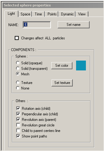
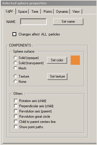
- The bottom-most window, called the 'Selected Sphere Properties Window', is acutally a set of pages, each of which is accessed by clicking on its corresponding tab, which allow you to manipulate the various properties, or characteristics, of the sphere which is currently selected in the tree of spheres in 'Sphere Hierarchy Window'. When a sphere is the selected sphere, it's name will be high-lighted in blue or gray. Note that exactly one sphere is selected in the tree at all times. Therefore, in order to change any of the properties of a particular sphere, you must first select that sphere in the tree of spheres by clicking on its name. Then you can affect the properties of that sphere, changing its name, color, size, axis, etc, using the controls in the property pages in the 'Selected Sphere Properties Window'. See figure C. FIGURE C LINK TOPIC 2 LINK
NOTE: The last property page in the bottom-most window, the page whose tab is labeled 'View', is not specific to the sphere currently selected in the tree of spheres. This page contains additional controls affecting the overall view of the automaton.
Figure A Sphere Hierarchy Window

Figure B Sphere Hierarchy Construction Window
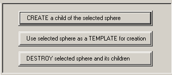
Figure C Selected Sphere Properties Window
Sphere Hierarchy Construction Window
The 'Sphere Hierarchy Construction Window' contains 3 buttons used to add and remove spheres from the sphere tree, and to designate one of the existing spheres as a template for future additions to the sphere tree. The three buttons have the following actions.
- 'CREATE a child of the selected sphere'
Whenever this button is pressed, a new sphere will be created using the current sphere template (if and only if a template has been set using the button described below), and it will be made a child of the current sphere which is selected in the 'Sphere Hierarchy Window'.
- 'Use selected sphere as a TEMPLATE for creation'
Whenever this button is pressed, the sphere which is currently selected in the 'Sphere Hierarchy Window' will become the template for all spheres created thereafter. The sphere attributes of the template sphere which are captured and then applied to subsequent spheres include the the radius and rolling-rate relationships that the selected sphere has with its parent, the orientation of the sphere with respect to its parent (inside or outside), the sphere's axis relative to its parent, whether the sphere rolls clockwise or counter-clockwise around its parent, all of the selected sphere's properties found in the 'Light' page of the 'Selected Sphere Properties Window', as well the selected sphere's point-set, and any dynamic modification parameters that have been set for the selected sphere.
- 'DESTROY selected sphere and its children'
Whenever this button is pressed, the sphere which is currently selected in the 'Sphere Hierarchy Window' and all of that sphere's child spheres will be deleted.
NOTE: There is no undo command. So be cautious when deleting spheres
Selected Sphere Properties Window
The bottom-most window, called the 'Selected Sphere Properties Window', is acutally a set of pages (each of which can be accessed by clicking on its corresponding tab) which allow you to manipulate the various properties, or characteristics, of the sphere which is currently selected in the tree of spheres in 'Sphere Hierarchy Window'. When a sphere is the selected sphere, it's name will be high-lighted in blue or gray. Note that exactly one sphere is selected in the tree at all times. Therefore, in order to change any of the properties of a particular sphere, you must first select that sphere in the tree of spheres by clicking on its name. Then you can affect the properties of that sphere, changing its name, color, size, axis, etc, using the controls in the property pages in the 'Selected Sphere Properties Window'.
The individual pages of the 'Selected Sphere Properties Window' and the properties of the selected sphere which they control are described below in left-to-right order.
- 'Light' property page
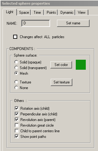
This page contains controls which affect the visibility, or appearance, of various parts of the sphere currently selected in the 'Sphere Hierarchy Window'. Note, however, that there is a single checkbox near the top of the page which is labeled 'Changes affect all particles'. When this checkbox is checked, any changes made on this page will actually affect all of the spheres which comprise the automaton's sphere tree. The attributes on this page are as follows.
- Sphere Name. This is the sphere's name which appears in the 'Sphere Hierarchy Window'. Its name can be changed by clicking the button labeled 'Set name'. When this button is pressed, the name for the selected sphere in the 'Sphere Hierarchy Window' will have a box around it, indicating that it can be edited. Type the new name for the sphere and hit 'Enter'.
- Sphere surface component. This box contains options affecting how the surface of the sphere is drawn. The options are to use the sphere's color (changable by clicking the button labeled 'Set color') and to draw an opaque sphere using that color, to draw a transparent spheres using that color, or to draw a mesh sphere using that color. Alternatively, the sphere can be drawn by wrapping a texture, or simple image, around the sphere, or you can choose to not draw the sphere at all. The default texture for all spheres is a map of the earth. To set a different texture for the selected sphere, click the button labeled 'Set texture' and then choose an image file to use as the new texture.
- Other sphere components. This box contains several checkboxes which determine the visibility of various parts of the sphere which is currently selected in the 'Sphere Hierarchy Window'. The various parts which can be made visible are as follows.
- Rotation axis (child). This is the axis about which the selected sphere is rotating as it rolls upon the surface of its parent sphere. If this box is checked, the axis will be drawn as an arrow from the selected sphere's center to its surface using the color of the selected sphere.
- Perpendicular axis (child). This is the axis perpendicular to the selected sphere's rotation axis. If this box is checked, the axis perpendicular to the sphere's rotation axis will be drawn as an arrow from the selected sphere's center to its surface using the color of the selected sphere. Making this axis visible allows one to see that the selected sphere is indeed rotating as it rolls upon the surface of its parent sphere.
- Revolution axis (parent). This is the axis of revolution of the selected sphere, necessarily parallel to the selected sphere's rotation axis. If this box is checked, this axis will be drawn as an arrow from the center of the selected sphere's parent sphere to the surface of the selected sphere's parent sphere using the color of the selected sphere.
- Revolution great circle. This is the circular path along the surface of the selected sphere's parent sphere that the selected sphere takes as it rolls upon the surface of its parent sphere. If this box is checked, this circular path will be drawn on the surface of the selected sphere's parent sphere using the color of the selected sphere.
- Child to parent centers line. This is a simple line segment connecting the centers of the selected sphere and the selected sphere's parent sphere. If this box is checked, the line segment will be drawn.
- Show point paths. If this box is checked, the paths taken by each of the points specified for the selected sphere will be drawn to their maxium length or to the length necessary to complete a closed loop through space. See the 'Points' page for a information about a sphere's points.
- 'Space' property page
This page contains controls which affect the spatial and spatial-temporal relationships between the sphere which is currently selected in the 'Sphere Hierarchy Window' and the selected sphere's parent sphere. The set of relationships required to uniquely a describe a pair of spheres in an automaton are as follows.
- Orientation. The selected sphere can either be rolling upon the inside surface or the outside surface of the parent sphere.
- Size. The radius of the selected sphere must naturally be related to the radius of another sphere. By default, the radius of the selected sphere is made relative to the radius of its parent sphere. But the radius of the selected sphere can also be made relative to any other sphere in the automaton's sphere tree by clicking on the new parent sphere in the listbox to the right of the label 'Radius = X * radius of sphere'. For example, if you set the value of X to be one-half in the above relation, then the selected sphere will be half the size of whatever sphere is selected in the listbox. Beneath this listbox is a button labeled "Set exact value of X". When clicked, a dialog will be displayed in which you can specify the exact fractional value for the ratio of the spheres' sizes.
- Axis. The selected sphere's axis is relative to the parent sphere's axis. The child sphere's axis is derived from the parent sphere's axis by performing two rotations, the first about the parent sphere's axis and the second about an axis perpendicular to the parent sphere's axis. There are two sets of controls opposite the labels 'Rotation about parent axis' and 'Rotation about perpendicular axis'. The controls opposite the first label determine the amount of rotation about the parent sphere's axis that the axis of the child sphere undergoes. The controls opposite the second label determine the amount of rotation about an axis perpendicular to the parent sphere's axis that the axis of the child sphere undergoes. Each of the two rotation values must be between 0 and 360 degrees.
- Revolution direction. The selected sphere can be revolving in a clockwise or a counter-clockwise direction around the parent sphere upon its surface. Therefore, you must indicate whether the selected sphere is revolving clockwise or counter-clockwise around the parent sphere when looking along the selected sphere's axis.
- Initial revolution angle. This is the initial angle of revolution of the selected sphere around the parent sphere from which the automaton's motion will commence. The value must be between 0 and 360 degrees.
- 'Time' property page
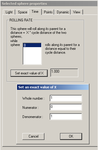
This page contains controls which affect the temporal relationship between two distinct pairs of spheres. Therefore, until at least 3 spheres comprise the automaton, this property page will go unused. The first pair of spheres in the temporal relationship contains the selected sphere and its parent sphere. The second pair of spheres can be any other sphere and its parent sphere. The temporal relationship between these two pairs of spheres is defined in sentence form wherein the nouns (which are the names of spheres), and a single decimal value X, must be provided. The sentence essentially says "The selected sphere will roll along its parent sphere for a certain distance in the same time that another sphere rolls along its parent sphere for a certain distance". The two distances mentioned are relative to the circumference of the parent or child sphere in each of the two pairs of spheres. By default the distances are relative to the circumference of the parent sphere in each of the two pairs of spheres.
The sentence thus begins "This sphere will roll along its parent for a distance = ( X * circumference) of sphere", which is followed by a listbox from which you can choose either the selected sphere or the selected sphere's parent. You can also change the value of X in the relation above from its default value. Thus far you've specified how much motion should transpire (actually the rolling distance) between the spheres in the first pair. Next you'll specify how much motion should transpire in the same time between the spheres in the second pair. The sentence continues " ... while sphere ...", which is followed by a second listbox from which you can select any sphere in the automaton's sphere tree except the selected sphere and the single sphere in the automaton which has no parent sphere. The sentence goes on " ... rolls along its parent for a distance = (1 * circumference) of sphere", at which point you must specify for the second pair whether the corresponding rolling distance is equal to the child or parent sphere's circumference by selecting the name of one of these spheres from the thrid and last listbox.
The value of X in the temporal relationship specifies the portion of the circumference of one of the two spheres in the first pair as the distance over which the spheres in the first pair should roll in the same time that the second pair of spheres roll upon one another for a distance that is equal to the circumference of one of the spheres in the second pair. The slider control and accompanying counter control allow you to gradually change the value of X in the relation above. By clicking on the button labeled 'Set exact value of X', you can provide an exact value for X. You can also set the range for the slider control by clicking on the buttton labeled 'Set range for X'.
- 'Points' property page
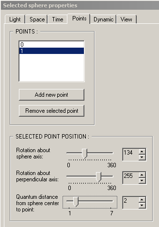
This page contains controls which allow you to specify a set of points whose positions remain constant relative to the sphere which is currently selected in the 'Sphere Hierarchy Window'. Furthermore, as the automaton carries out its movement, the paths taken by each of these points can be drawn. Each sphere in the automaton has a single point intially, which is located at the sphere's center. It is named '0' in the list of points and cannot be removed. To add a new point to the selected sphere, simply click the button labeled 'Add new point' and a new point will be added to the list. To remove an existing point, select it in the list of points by clicking on its name and then click the buttton labeled 'Remove selected point'.
To specify the position of one of the sphere's points, select the point in the list by clicking on, and then adjust the three groups of controls, each consisting of a slider control and a counter conrol. The first two groups of controls together determine the position of the selected point, as two perpendicular rotations relative to the selected sphere's axis. The last group of controls determines the distance of the point from the selected sphere's center as an integral multiple of the selected sphere's radius.
NOTE: As you adjust any point's position using the slider controls, an arrow from the selected particle's center to the specified point position will be momentarily drawn to faciliate the process of positioning a sphere's points. This arrow will not be visible when the automaton recommences its motion.
- 'Dynamic' property page
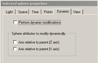
This page contains controls which allow you to indicate that the sphere which is currently selected in the 'Sphere Hierarchy Window' should undergo dynamic changes to one or more of the spatial relationships it has with its parent sphere. The indicated relationship will be repeatedly updated, and the automaton will be re-displayed for each value. Since these values are angles, they will be reset to 0 upon reaching a value of 360 degrees.
The controls on this property page work as follows. At the top of the page is a checkbox, controlling whether the selected particle should carry out the dynamic changes described by the remaining controls on the page. If the checkbox is not checked, then the selected sphere's relationships with its parent will not change. Below this are two additional checkboxes that indicate which spatial relatiohships of the selected sphere will change. The two options are described below.
- Rotation about parent axis. The selected sphere's axis is derived from its parent sphere's axis by performing two rotations, the first about the parent sphere's axis and the second about an axis perpendicular to the parent sphere's axis. This is the first of the two rotations determining the selected sphere's axis.
- Rotation about perpendicular axis. The selected sphere's axis is derived from its parent sphere's axis by performing two rotations, the first about the parent sphere's axis and the second about an axis perpendicular to the parent sphere's axis. This is the second of the two rotations determining the selected sphere's axis.
- 'View' property page
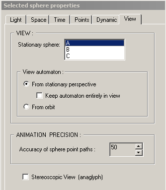
This page contains controls which do NOT affect the sphere which is currently selected in the 'Sphere Hierarchy Window', but affect the overall view of the automaton.
The page's controls which are contained within the box labeled 'VIEW' affect a couple of things defining how the automaton is viewed. First of all, because of the hierarchical, or tree-like, structure of an automaton, wherein each sphere is the child of another sphere, and in which the spatial and temporal relationships that a sphere has are always relative to another sphere or relationship, it is naturally true that any of the spheres that comprise an automaton can be made the stationary, or non-moving, sphere as the automaton carries out its movement. The relationships amongst the spheres in the automaton's sphere tree are still valid and uniquely define a pattern in space and in time. Therefore, you can specify the particular sphere in the automaton's sphere tree which will be stationary by selecting that sphere's name from the listbox to right of the label 'Stationary sphere'. Some curious relationships can be seen by constructing an automaton and then making different spheres the stationary sphere.
The next group of controls, contained in the box labeled 'View automaton' determine the view of the automaton by moving the viewpoint, or camera location. First a choice must be made whether to view the automaton 'From a stationary perspective', in which case the viewpoint does not move as the automaton moves, or whether to view the automaton by making the viewpoint 'From orbit'. If the automaton is viewed from a stationary perspective (the first option), then there is the additional option to 'Keep the automaton entirely in view', in which case the program takes control of the zooming capability (Viewing controls) and ensures that all of the paths taken by points of the automaton's spheres remain in view. If the automaton is viewed 'From orbit' (the second option), then that sphere whose motion should be followed can be selected in the listbox below that option. The effect of this option is that the viewpoint kind of flows in harmony with the selected sphere's motion.
The group of controls contained within the box labeled 'ANIMATION PRECISION' control the accuracy of the automaton's movement and consequently affect the smoothness of the paths taken by the spheres' points. The accuracy can be adjusted by clicking on the up and down buttons on the spin control.
The lone checkbox at the bottom of this property page labeled 'Stereographic View (anaglyph)' determines whether the rendering of the automaton is done using the regular perspective projection of 3-dimensions or whether the appropriate left-eye and right-eye images are generated in red and blue respectively for use with 3D glasses.
 Automaton3D Quantum


